The GPUs (Graphics Processing Units) also called graphics cards are important parts of the modern day computing systems. They also perform complex visual tasks, such as processing 3D images, speeding up video playback and performing AI-based workloads. At the centre of any graphics card is its PCB (Printed Circuit Board), which is the basis around which all the necessary elements are incorporated. In the present article, we would discuss structure, functionality, and important points of graphics card PCB.
What is PCB?
A Printed Circuit Board (PCB) is a flat board of insulating substance which is usually fiberglass but has a covering of copper conductive pattern (circuit). PCBs are found almost everywhere in an electronic product as a mechanical backbone and an electrical connection. With respect to a graphics card, the PCB is the core structure that supports the GPU chip, the memory modules and the power delivery units and the connectors.
The architecture and pattern of a graphics card PCB is vital to the performance, thermal efficiency, reliability of web servers. The complexity of PCB design assists in realizing the optimization of GPUs to high-performance computing.
Important parts of PCB Graphics card
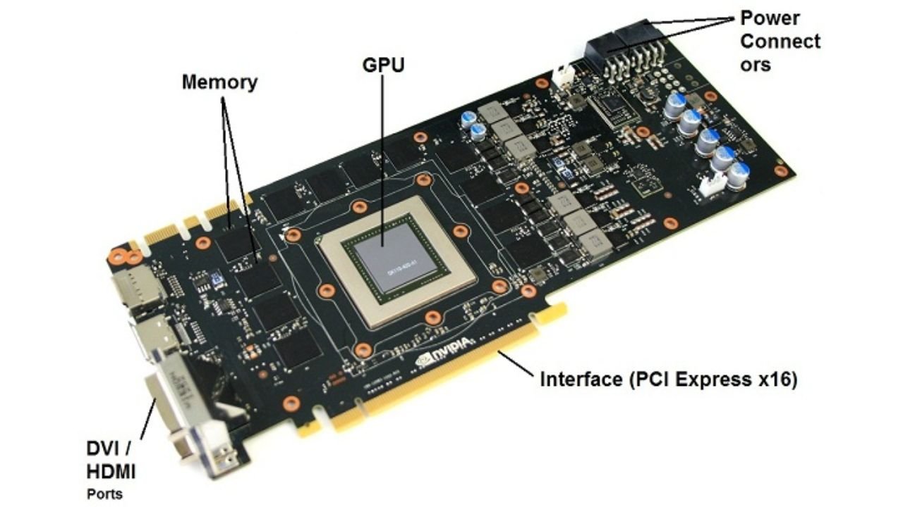
- GPU Die The graphics card uses a GPU die as the central processor. It carries out millions of computations within a one- second duration in order to provide images and videos. The die is placed on the PCB and is enclosed with the other necessary components to be able to perform its functionality.
- VRAM (Video RAM) Video RAM is used to give the GPU a fast access to the data required during the process of rendering. Contemporary graphics cards usually revolve around GDDR (Graphics Double Data Rate) memory (GDDR6 or GDDR6X). On the PCB, the VRAM chips are placed around the GPU in order to reduce latency.
- VRM (Voltage Regulation Module) VRM is the very important component of the PCB which delivers stable power to the GPU. It is a combination of MOSFETs, inductors and capacitors, which are needed together to reconstitute the power supplied by the PSU ( Power Supply Unit) to voltages needed by the GPU.
- Power Connectors Graphic cards need more power than the one provided by the motherboard. The PCB features connectors (usually 6-pin, 8-pin or even 12-pin) that get supplied directly by the PSU. These connectors are connected the VRM to regulate power.
- PCIe ConnectorThe PCI Express (PCIe) connector is the port in which the graphics card uses to speak to the motherboard. The PCB features a slot edge connector to plug into one of PCIe slots on the motherboard.
- Capacitors and Inductors These are passive components that are dispersed in the PCB to control power stability and calm down voltage variations. Inductors and capacitors are of high quality and would help in the overall lifespan and workability of the graphics card.
- Display Output ConnectorsAt the rear I/O panel the PCB ends with connectors supporting the multiple display methods, HDMI, DisplayPort, DVI. These connectors enable the user to connect monitors and other display devices to graphics card.
- Cooling System Interface The cooling system interface is not an electronic component but the PCB layout should be able to accommodate the cooling system. The cuttingly holes and the thermal pads are posited smartly to maintain the heat resistance of the GPU and the VRAM.
Layers Graphics Card PCB
In high performance graphics cards, PCBs are mostly multi-layered. The multilayers assist in multiplexing of intricate conductivity which guarantees signal stability and improved power dispersal. A standard graphics card PCB can be between 6 and 12-layered and each layer fulfills a particular role:
- Top Layer: The top layer contains most of major elements such as GPU, VRAM and a majority of the VRM components.
- Signal Layers: signal layers can be used to route high speed data signals between components. This should also be well routed and spaced to prevent interference and crosstalk between signals.
- Power layers: Specific power layers will guarantee that the varying voltages evenly spread over the PCB. The stable operation, particularly on the heavy workloads, is impossible without such layers.
- Ground Layers: Ground layers serve as reference planes among the signals and assist in mitigation of electromagnetic interference(EMI). They are also responsible in enhance thermal dissipation.
- Bottom Layer: The bottom layer could have extra components and tracks. It also has the solder points of the PCIe connector and other interface functions.
The Compulsory of PCB Design
There are a number of issues associated with the design of graphics card PCB:
- Thermal Management GPUs become very hot when in motion. The PCB has to be made in such a way that cooling facilities are encouraging, the appropriate location of parts and mounting heatsinks and fans.
- Signal integrity High-frequency data signals are prone to interference and noise. Trace routing and spacing must be well designed to meet signal integrity requirements of the designers.
- Power Feeds The modern GPUs are capable of consuming hundreds of watts of power. Maintaining constant and efficient power delivery is also based on careful production of the VRMs and impeccable components.
- Form Factor Limits All graphics cards need to adjust to form factor size limitations, to be able to fit in most regular PC cases. This restricts the space in which to place components, and demands clever layouts.
The Significance of PCB Quality of Overclocking
This is done by means of overclocking the GPU to run faster than the manufacturers have recommended. Quality PCB is needed in stable overclocking. Influencers which affect PCB quality are as follows:
- Strong VRM Design: The design has more phases and high-quality components to support more power delivery without overheating.
- Heavier Copper: Heavier copper increases the ability to carry more current and reduces heat.
- Improved cooling: Custom PCBs typically have more efficient cooling options, which means they have a larger overclocking margin.
Basic Troubleshooting of the Common PCB problems
- Power Problems: If a graphics card fails to turn on, then the power circuit components may not have worked or the power pins may be damaged.
- Display Artifacts: The presence of corrupted visuals or artifacts may be caused by VRAM or signal integrity PCB problems.
- Overheating: The corresponding overheating of the PCB can be caused by insufficient cooling or the lack of heat conduction between the board components and the cooling system.
- Physical Damage: This includes cracks or warping of the PCB which makes it malfunction or fail completely.
The Trend of Graphics Card PCB in the Future
Due to the further development of GPU technology, the design of PCB will evolve. Among the major trends are the following:
- Shorter Node Size: As the manufacture of GPUs proceeds to smaller manufacturing nodes, PCBs will have to facilitate denser components.
- Better Power Efficiency: VRM will be improved in design and materials used in it which will make it more power efficient and produce less heat.
- Flexible PCBs: The study of flexible PCBs might result in a new form factor of GPUs.
- Integrated Cooling Solutions: Future PCBs can have built-in liquid cooling loop or cooling channels to provide improved cooling.
Conclusion
The Graphics card PCB so much more competent than a mere board with the component, in that it is a marvell of multi-layered computing that spells the difference in the workability, efficiency and lifespan of the graphics card. Every part of PCB design is important, whether it is maintaining constant power supply or working with fast signals. As a hardware enthusiast, an overclocking professional, or somebody simply wondering about how a graphics card performs its incredible work, being able to understand the part the PCB plays helps you learn more about this important hardware component. With further advancement of technology, the quality of PCB designs is going to push more advance graphics card generation.
Read more: https://wildlabsky.com/