In this world, we will learn about circuit boards and multimeters. Have you ask yourself what happens inside your electronic gadgets? What allows the individual parts of a microchip to collaborate and produce excellent functions? First, we want to discuss PCBs which stand for Printed Circuit Boards, then learn how to use a multimeter to test them.
Being able to check a PCB with a multimeter is helpful, no matter if you are experienced in DIY or just trying to fix electronics at home. With it, you are able to recognize errors in the circuit, understand the reasons behind them and maybe avoid paying for costly fixes or updates. The electronic store has a wide selection of PCB designs and multimeters, meant to help professionals and keen amateurs get a reliable and usable circuit assembly.
Place your multimeter on hand and let’s get learning together! We will explain how to check the voltage, test continuity, examine resistors, capacitors, diodes, transistors and find solutions to common problems. When the tutorial ends, you will have useful information that can help you shine as an electronics expert. Here’s where we start!
What are Circuit Boards
Virtually every electronic device we have today relies heavily on circuit boards which are also called PCBs. A printed circuit board has a thin, flat surface that is made of non-conductive substances like fiberglass or epoxy resin and it has lines on its surface to link all the electronic parts.
The main goal of a circuit board is to allow these elements to work together without any issues. Envision your favorite products’ central nervous system when thinking about electronics. Circuit boards help make possible the useful features in computers, cellphones, kitchen appliances and modern vehicles.
Networks such as these are built with various layers that carry out certain jobs. The top level of the PCB consists of copper minerals that allow electrical signals to travel. Below those visible layers, there are many special patterns made for managing power distribution, grounding and signal integrity.
Good and reliable circuit boards are created by doing every design aspect with due care. The board’s functionality and long-lasting life depend a lot on its trace width, component spacing and thermal control.
As technology keeps advancing so quickly, circuit boards are also developing. It is now important to miniaturize components so that devices have more features in smaller shapes. That results in PCBs with small areas and plenty of electronic components – making production processes even more exacting.
All in all (as directed), knowing how these systems interact is very important when solving problems or examining their health with a multimeter. If you know the basics of how circuits function on these boards, you will be confident in using your electronics.
What is the use of a Multimeter?
Anyone interested in electronics would find a multimeter to be important. You can measure many things at once through the Multi Function Tester’s convenient handheld form. With a multimeter, it is possible to test voltage, current and resistance in electronic circuits.
Multimeters are mostly known for measuring voltage. The term voltage describes the difference in charge between two points in a circuit. Place the red probe on the positive terminal and the black probe on the negative terminal to decide if the circuit is turned on or off.
As well as checking voltage, a multimeter enables you to test if a circuit is complete. The purpose of continuity testing is to see if a smooth path for current exists between two points in a PCB. This function is very useful when checking or identifying bad wires.
Another significant use of a multimeter is to check resistors. Resistors passively limit the amount of current in different electronic systems. To ensure your resistors are working, attach the multimeter probes to both ends and watch the resistance reading to know if it is correct.
Need to test the health of your capacitors which store electricity? Your digital multimeter will help you out. In capacitance mode (F), you can watch the level of charge in capacitors to make sure they work properly.
With particular advanced models of multimeters, you can directly confirm if diodes in your circuit board are correct by checking their responses to positive and negative voltage signals.
All in all, having and being able to use a good digital multi-meter is very useful whenever you need to repair or build electronics.
Testing Voltage
Peak voltage is an important thing to measure every time you use a multimeter to check a PCB. It permits you to check if the wires handle the appropriate voltage and if you notice any disturbance or unexpected changes that might suggest something is wrong.
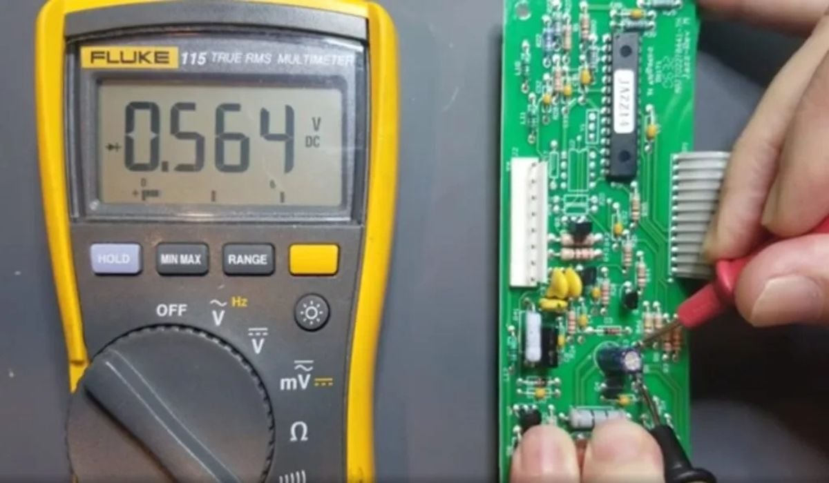
Pick the correct DC or AC voltage setting on your multimeter before checking for voltage. After that, attach or place the black probe at the negative or ground terminal of the component. After that, place the red probe on the positive terminal and review the reading shown on the multimeter.
Be sure that the results for every component are within the same range each time. Should you measure volts much different from what you predicted, a fault in the component or wiring may be the issue.
When you are testing voltage in live circuits, stay safe by wearing gloves and goggles and watch out for any electrical dangers.
Checking the voltage along your circuit board’s routes helps you identify any problems and secure reliable and correct working of all its parts.
Testing Continuity
In a PCB check with a multimeter, continuity testing is very important. It makes it possible to see if the circuit is complete and electricity can pass freely or if there are gaps in the circuit.
We must switch our multimeter to the continuity mode to do the test. If there is a beep, it means that electricity can flow between two points in the circuit board. It makes it possible to locate damaged wires, cracks in connections or broken parts.
The next step is to touch one probe to the beginning of the trace or component and the other probe to its end. A continuous beep sound is a sign that the part of the circuit with current has no issues.
If there is no beep, it suggest that part of the connection is disconnected. Tracing along various points on the PCB in this manner allows us to spot the exact location of a breakage.
Be sure to turn off the power supply to PCBs and discharge them before starting any test with your multimeter.
To identify any faults, test continuity with a multimeter and fix them as efficiently as possible. It is very useful for any expert in electronics or for technicians who need to diagnose errors on their printed circuit boards.
Testing Resistors
Resistors are necessary in circuit boards since they control the rate at which electrical current flows. They can have different values and to check if they are working properly, you can use a multimeter. This is how you can measure resistors using a multimeter.
You should make sure that no power is connected to the circuit board at the outset. By doing this, you will not cause damage or harm to yourself by accident.
Make sure your multimeter is on the resistance (ohms) mode and that the range you have selected is correct for the resistor. Set the heat on the highest level, then reduce it if you have to.
After that, place each probe from your multimeter on one of the resistor’s leads. It does not really matter in which direction the resistors go as they do nothave polarity.
Watch the number displayed on the multimeter’s screen. If it has a value near the resistance number given on the resistor, it proves that it is working properly.
Any readings that are substantially different can be because of an issue with the resistor. It could be broken and require a new one to be fitted.
You should always manage resistors carefully because they are a delicate type of electronic part. It’s best not to place your fingers on the metal parts of batteries, as your oils can change how they work.
Test your resistors regularly to locate any issues in circuit boards and for the best results from your electronics.
Testing Capacitors
Since capacitors can hold and release energy, they are important elements in electronics. To avoid problems, capacitors must be tested on a regular basis. It is helpful to use a multimeter to check the voltage of a battery.
Put your multimeter in the capacitance mode before checking the capacitor. Attach the red wire from the multimeter to the capacitor’s positive terminal and the black wire to the negative one. If the capacitance is within the prescribed bounds, it will be shown on the meter.
Should you find a reason to check the resistance on a capacitor, put your multimeter into its resistance mode and test as directed below. You should discharge the capacitor before you begin your test by connecting a resistor or insulated wire across the tourniquet’s terminals. After that, attach each probe to a different terminal of the discharged capacitor and check if you notice any resistance and whether this value changes over the course of time.
Be sure to connect the capacitors correctly, as they have polarity, while using them for testing. Noticing low capacitance values or different resistance readings than before might tell you that your capacitor requires changing.
the steps to testing a circuit board with a multimeter
- Visual Inspection:
Search for scorched items, parts that have come off or unconnected wires.
Put in place the components of the multimeter.
With the multimeter on, opt for the function you require, whether it is voltage, resistance or continuity.
- Continuity Test:
Use probes on traces or components and if the beep signals, this indicates the circuit is unbroken.
- Resistance Measurement:
Put the probes on the components and check resistance by comparing the readings to what you expect them to be.
- Voltage Measurement:
With the power still on, use the multimeter’s voltage function and touch the probes to where you want to measure.
- Diode Test:
Use the diode mode on the multimeter and test if a small voltage drop appears from one side to the other side of the diode.
- Capacitance Measurement:
Turn the power off, move the dial to capacitance mode and measure at the capacitors’ terminals.
Look at all the power rails in the network.
Make sure the voltage on the power supply rail is as indicated on the diagram or datasheet.
- Thermal Inspection:
Take advantage of a thermal camera to spot any hotspots that could show problems in your system.
- Look at the Solder Circuits:
Go over the soldered joints while checking for signs of cracks or signs of cold joints.